Showing posts with label Information Model. Show all posts

Saturday, February 14, 2026

Seven IEC 61850 Model Documents Published for Public CDV Comments

Please note that seven IEC 61850-7-xxx model documents have been published for CDV comments on 2026-02-13. The following documents are available for public comments until 2026-04-10:

IEC 61850-7-4 ED3
Communication networks and systems for power utility
automation - Part 7-4: Basic communication structure -
Compatible logical node classes and data object classes -
Core

IEC 61850-7-40 ED1
... Common part

IEC 61850-7-43 ED1
... Primary equipment

IEC 61850-7-44 ED1
... Instrument transformers

IEC 61850-7-400 ED1
.... Substation automation

IEC 61850-7-401 ED1
... Protection

IEC 61850-7-440 ED1
... Power quality metering

Enjoy!

Friday, October 10, 2025

What is a model in the context of IEC 61850?

A model is a model is a model ... huch.

The question is: What does a model provide? In short: It provides an external visible PATH to an actual value of something, e.g., a voltage or temperature. A model of my home is not something where I can life in! It shows where the rooms, stairs, ... are ... 

The leaves (or end points) of the model in the IEC 61850 TREE (of a model) are NOT where the actual value reside! Basic Data Attribute (BDA) in IEC 61850 are the leaves of the trees. 

Just a minor comment on the BDA: I found this: "This is the lowest level, where the actual value resides." IEC 61850 defines models that hide the storage location of an actual value. The BDA is a PATH to the actual value. The value resides "behind" that model. The BDA holds an externally non-visible or non-accessible reference to the actual measurement value or status.

When reading the current value of the phase A of the MODEL MMXU1 you send a read request with the PATH: "LD/MMXU1.A.phsA.cVal.mag.f". This PATH is translated into the direct or indirect storage location of a specific IED. How that is implemented, depends on the architecture of the interface and application software. It may even be mapped to an underlying fieldbus specific address (e.g., Modbus coil 2828). When the read request is received, the IED uses Modbus to read the actual value from coil 2828. In this case the actual value resides beyond the IED with its MODEL. The IED needs a non-visible specific mapping from the PATH to the Modbus register.

The models in IEC 61850 describe a virtual world in the following sense:

If it's there and you can see it         It's REAL
If it's there and you can't see it         It's TRANSPARENT
If it's not there and you can see it It's VIRTUAL
If it's not there and you can't see it It's GONE
Roy Wills

I hope that helps to understand the Models in IEC 61850.

This virtualization has an impact on how an IEC 61850 Stack (is not defined in IEC 61850 what a stack is) you purchase maps the leaves of the model to the location of your actual values.

Thursday, March 5, 2020

IEC 61850 und eCl@ss - Interoperabilität durch standardisierte Informationsmodelle

Interoperabilität durch standardisierte Informationsmodelle

Der „eCl@ss“-Standard ermöglicht den digitalen Austausch von Produktstammdaten über Branchen, Länder, Sprachen oder Organisationen hinweg. Wie ein Produkt nach „eCl@ss“ mit Merkmalen nach IEC 61850 ganzheitlich zur Interoperabilität auf den Ebenen Produktbeschreibung, Systemengineering, Gerätekonfiguration, Informationsaustausch und Protokolle ergänzt werden kann, zeigt der nachfolgende (frei herunterladbare 5-seitige) Beitrag im etz Heft 12/2019 (Link siehe unten):


Hier klicken, um das gesamte etz Heft 12/2019 inklusive des obigen Beitrags (Seiten 30-35) herunterzuladen. 

Tuesday, November 19, 2019

The History Of The IEC 61850 Modelling

The standardization of IEC 61850 started in 1995 when the IEC TC 57 Working Groups 10, 11, and 12 had been setup. Later all projects have been moved to the Working Group 10 - that is still (very!) active today.
Prior to the new project proposal for IEC 61850 the EPRI UCA project developed core models for many signals and communication services. UCA used a simple table notation for defining "models".
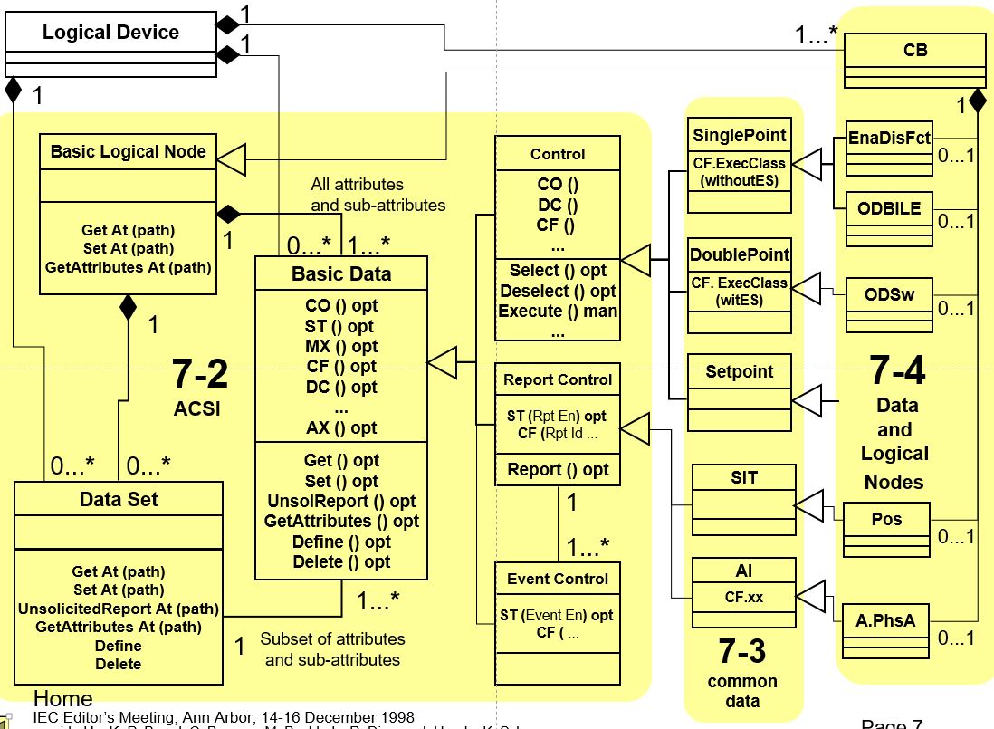
The experts involved have discussed several options how to model the signals. In December 1998 the editors of the core documents (including myself) met in Ann Arbor (MI, USA).


We discussed modelling with ASN.1 or our own notation:


we were not quite happy ... then we discussed trying UML … walked across the street to the University bookshop to purchase some 10 Books about UML Modelling. I purchased several books, too:


… a senior development manager of protection relays was strictly against UML … he said, it will never be used for protection and automation. Some weeks later I met his engineers in their office … and saw that they used UML for developments …

Later I tried OWL with some success:


Experts involved in CIM (Common Information Models) used UML - with the SPARX tool Enterprise Architect (EA). It took several years before UML (and EA) was used to define all models of IEC 61850. Today (end of 2019) almost all models and other definitions are managed with the EA - it is a big success! The latest version comprises the following parts:


There are tools available to export parts of the model from EA as Word documents, html pages, pdf ...

Example of a model:


With the application of the SPARX EA we have a single source of all crucial definitions.

Note: The EA package "IEC61850Domain" is only available for the experts writing, publishing and maintaining the various standard parts.

Some exported documents (the so-called code components) are available for free access:
Click HERE for accessing these documents.

Thanks to the experts that have continuously pushed for using UML and EA. It took several years ... and it was not easy for engineers to use a formal language and tool to get where we are today.

These days the EA is used also for many other tasks: use cases, design state machines like for IEC 61850-90-16 (System management), ... IEC TC 57 has done a good job in using UML for CIM and IEC 61850. But another generation of engineers is needed to understand the full benefit of using UML.

Saturday, February 9, 2019

Difference between IEC 60870-5-104 and IEC 61850

There seems to be a growing interest to understand what the difference is between IEC 60870-5-104 and IEC 61850. There have been many discussions, complaints, and frustrations ... no wonder.Here is what I have answered to somebody this week:

Dear xxx,

I guess I got it ... you are analyzing the communication inside a station ... to the IEDs (protection, control, ...).

The IEC 60870-5-104 plus a lot of utility or project specific (signal) engineering will do the job – has done it for decades.

The engineering is the key issue when comparing the two standards … if you can compare them at all!!

IEC 61850 offers a lot more than 104 or DNP3 …


From a message overhead point of view, you can say, that both are more or less the same ... because they use both Ethernet and TCP/IP. There is no benefit to use one or the other.
It is likely that IED vendors will mainly focus on IEC 61850 ... and may get rid of 104 in the long run.
I have always said that utilities using 104 in all substations should continue to use it – until they build new substations or do major refurbishments. There is no need to replace a running 104 solution with IEC 61850 ...
Another issue is: To use GOOSE for interlocking … to get rid of copper … or use it for tripping … and use sampled values some time down the road.
Finally there is an issue with manpower: If the utility has senior experts in 104 close to retirement … they should wait until they have retired. Yes! I have seen many old engineers not willing to learn something completely new!!
Click HERE for a detailed comparison written by domain experts.
Hope that helps a bit more.
Best Regards,
Karlheinz

Monday, August 7, 2017

IEC 61850, Sensors, and Cyber Threats

Sensors all over will be more important in the future: First to automate processes and second to monitor the automation systems.
The other day I found a very serious report on compromising automation systems under the title:

ICS cyber threats are morphing into compromise of plant functionality – do we have the right tools? 

The report by Joe Weiss is worth to read.

Click HERE for reading the complete report.

The discussion is about compromising an actuator (Valve, ...)  and let the physics do the damage!

Joe resumes: "Without sensor monitoring, it is NOT possible to see the precursor to these kinds of conditions until it is too late."

I have discussed the reported issues with an expert of valves in industrial process control applications. He confirmed that the cavitation (bubble or Wasserblasen) effect is known for long. But there are only a relatively few applications of (vibration) sensors installed to measure the noise produced by cavitation (see video at Youtube) to figure out that something is going wrong.

IEC 61850 has a bunch of models and services to support sensors:


and event reporting:


The quality attributes that come with all values could be used to flag that the value is valid or not. Additionally the sensor may have a health problem (figured out by a diagnosis routine) that can be reported using the TTMP.EEHealth.stVal attribute (EE - external equipment).

All models and services have to rely on good hardware and software! Or we get: Garbage in - Garbage out!

In our seminars and hands-on training courses we discuss these and many other topics in detail.

Thursday, January 28, 2016

IEC Committee Draft (CD) 61850-7-420 Ed. 2.0 just published

IEC TC 57 has just published the 57/1655/CD:

IEC CD 61850-7-420 Ed. 2.0: Communication networks and systems for power utility automation -
Part 7-420: Basic communication structure - Distributed energy resources logical nodes

Commenting closes 2016-04-08.

Attention is drawn to document 57/1658/DC which is circulated in parallel and which reflects a draft IEC TR 61850-7-520 and which contains the main guidelines on how to use the data models contained in the present CD.
.
Since both documents are closely linked IEC national committees are invited to develop their comments in parallel on the present CD and on 57/1658/DC.

The major technical changes with regard to the previous edition are as follows:

  • Corrections and clarifications according to information letter "IEC 61850-technical issues by the IEC TC 57” (see document 57/963/INF, 2008-07-18);
  • Extensions regarding IEC 61850-90-7 (object models for converters in distributed energy resources (DER) systems);
  • Some logical nodes in IEC 61850-7-420:2009 that were not specific to distributed energy resources have been transferred to IEC 61850-7-4 Ed. 2.1 and have been removed from this edition of IEC 61850-7-420 (see also Annex A);
  • The definitions of logical nodes in this edition of IEC 61850-7-420 have been updated using the table format introduced in IEC 61850-7-4 Ed. 2.1;
  • Most of the modelling examples and background information that was included in IEC 61850-7-420:2009 has been transferred to IEC 61850-7-520
This CD is not available publicly as a CDV. The CDV may be available later this year. 

Stay tuned to this blog.

Wednesday, March 11, 2015

What Does Complexity of a Protocol Mean?

There is always a discussion on one protocol being more efficient and less complex than another or all other. Does this discussion help? I don’t think so.

The key issue is the “SYSTEM” – which is MUCH more than a protocol.

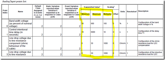
Let’s discuss briefly the configuration of a device with regard to reporting a value based on a deadband configuration and the range and multiplier of an analog value.

Usually the deadband values and range configurations and other crucial information are specified in a pdf file or – if you are lucky – in an excel sheet or XML file. So, to interpret a message the receiver has to know the configuration. The tables contained in the pdf file (below) have to be translated by somebody manually … and how can I find out in 10 years from now, what the limits of the Band width voltage are? Hm. No idea?! Usually you cannot ask the device. So, what now?

I am sorry, if you don’t have the pdf you may guess what the limits are – but you don’t know. Maybe somebody from the vendor is still there and can answer the question.

Example of a DNP3 SPECIFICATION - DEVICE PROFILE

Excerpt on deadbands and configuration:

image

image

A good thing is, that many vendors publish these files. Sur, you never know if they are up-to-date or applicable for your device you installed some time ago.

The information models of IEC 61850 provide dedicated attributes for a value that provide these meta data like deadband configuration, min, max, multiplier, SIUnit. These attributes could be used in the corresponding SCL file only or they could additionally be exposed by the device and made accessible through a simple read message.

With IEC 61850 in place we could easily expose the limits of power production and load and further attributes. The logical node MMXU (IEC 61850-7-4) could be used for the limits in which a value is valid:

Data Object TotW of class MV (measured value, IEC 61850-7-3) - Total active power (total P)

could provide the actual value, quality, range, Scale, limits, units, deadband in the details provided through the MV CDC:

mag.f deadband filtered AnalogueValue coded as floating point
q Quality
range ENUMERATED normal|high|low|high-high|low-low (out of range would change quality value)
rangeC RangeConfig:
hhLim
hLim
lLim
llLim
min
max
sVC ScaledValueConfig (scale and offset) for Integer values
db Deadband filter in % of range (min – max)
units SIUnit and multiplier

min: the min (minimum) attribute shall represent the minimum process measurement for which values of i or f are considered within process limits. If the value is lower, q shall be set accordingly (validity = questionable, detailQual = outOfRange).

max: the max (maximum) attribute shall represent the maximum process measurement for which values of i or f are considered within process limits. If the value is higher, q shall be set accordingly (validity = questionable, detailQual = outOfRange).

In our case, the TotW for the CHP generator may be limited between 0 W (min) and 35 kW (max). A value of “minus 600” MW would have to be flagged as questionable and outOfRange !! Negative values and values higher than 35 kW would be flagged out of range!

The receiver (a control center) could check the limits of the values (either by reading the range configuration online by a service or getting it from the corresponding SCL file). It could figure out that the range is 0-35 kW. Even if the gateway (RTU) would send “minus 600” MW (load) … the CC could understand that this is a bad value – recommended not to use.

The ScaledValueConfig exposes the scale factor and offset value – required to interpret an integer value.

The deadband db defines when to report a new value: when a change of the value is “+/- db of the range”: a range of 100 A and db=2000 (2 %) means –> every change of 2 A will be reported; the last reported value was 78 A, then the next report will be issued when the value reaches 76 A or 80 A.

The units contain the SIUnit (e.g., A) and the multiplier (10**0 –> 1).

The meta-data of the measured value serve as a means to help interpreting the plausibility and validation of a value communicated.

To focus on a message “Report a changed value based on a deadband configuration” and discuss which protocol does it more efficient is not helpful! Modbus can communicate the total Power – as can any other protocol. But: HOW to INTERPRET a received value? Is the value within the limits defined for an application? Is the value given in W, kW, MW or GW??

A system should be able to provide more than just A value – all crucial meta data that help to interpret the value are needed in any case. Either you get it – or …

Please focus on the “System” – a holistic approach is what we need.

This blog post will likely not stop protocol efficiency discussion … ok. And?

If it makes you happy when you discuss protocol issues … do it.

Thursday, September 25, 2014

IEC 61400-25 Part 2 and Part 3 CDV approved

The following two documents (CDV – Committee Drafts for Vote) have been accepted by 100 per cent of the Members of IEC TC 88 (in August resp. in September 2014):

Wind turbines – Part 25-2 (Edition 2): Communications for monitoring and control of wind power plants – Information models

Wind turbines - Part 25-3 (Edition 2): Communications for monitoring and control of wind power plants -Information exchange models

Both parts will be published as FDIS soon.

The Information Models are revised to make them consistent with the many other models defined in IEC 61850-7-x. For example in LN WTUR several names of DataObjects change:

SptDmdW to DmdWSpt
SptDmdVAr to DmdVArSpt
SptDmdPF to DmdPFSpt

The Edition 2 of the models is a major step towards harmonization of the information models. The wind power plant objects are now very stable – they are also incorporated into the UML master maintained by IEC TC 57 WG10, WG 17, WG 18, and JWG25 (TC57/TC88):

image

The changes proposed in conjunction of the CDV comments on part 25-2 have already been used for the UML model. Now we have a very stable and harmonized set of information models that can be used for the whole power delivery system – all over.

Additional models are under way, e.g., for condition monitoring (90-3).

Thanks to the UML team!

Friday, February 28, 2014

What are the Benefits of IEC 61850?

The question “What are the benefits of IEC 61850” has different flavors and multiple answers – it depends on what are you looking for. If you are looking just at the communication protocol, there are answers like:

  1. The client/server protocol (MMS) is a unified solution standardized some 25 years ago. It is a stable standard – unlikely to change in the future and accepted all over for many years.
  2. The GOOSE messaging is very unique and provides real-time information exchange in the msec range – accepted all over
  3. The Sampled Values messaging provides a unique solution for exchanging samples of currents, voltages, vibration measurements accepted all over.

If you are looking at the information models, there are really many crucial models defined and in use. No other standard (I am aware of) has such a rich set of information models that expose process information in a standardized way – all over accepted.

There is – of course – the crucial issue on the configuration language. In this post we will discuss the benefit of a unified model that allows to hide the different vendor-specific signal lists for Modbus communication in two different power quality meters. In the end, the unification of specific information profiles (or subsets) for, e.g., the electrical measurements makes IEC 61850 different compared to any other solution I know.

The power quality monitors used are: Janitza UMG 604 and Acuvim II. Both meters provide many measurements of the electrical system. The signals can be communicated by Modbus. Usually each vendor has a different approach to define the lists of signals – and especially the indexes used for the vary same signal is quite different and have to be mapped manually to any application – again and again. There is no way to agree on a single unified Modbus signal list that can be applied all over. The next figure shows the two devices, their signal “phase voltage” with different identifiers and indexes.

image

The unification of the information model is implemented in a simple gateway (com.tom BASIC 5.1). The gateway is based on a WEB-PLC that maps the incoming Modbus signals to IEC 61850 models. The IEC 61850 model uses the same logical node class and type. The type MMXU_0 is the subset of the MMXU class used in this application (of four data objects – as can be seen in the icd file). The instance MMXU1 can easily be “copied” to build a second instance: for the Acuvim II meter. Both instances use a unique MMXU logical node type (contained in the icd file). The model can be used to configure the IEC 61850 server device and an IEC 61850 client (in this case the IEDScout) as shown in the next figure.

image

The gateway solution is reasonable in case just a limited number of applications need the information communicated by IEC 61850.  The next step could be to integrate the “gateway” into the meter housing, as shown in the next figure:

image

The “heart” of the gateway (we use) is the Beck IPC@CHIP controller that could be applied as a subsystem in the meter. It manages the complete IEC 61850, IEC 61400-25, IEC 60870-5-104 or DNP3 communication.

The IEC 61850 models are the same as before in the case of using a separate gateway box. From a client point of view there is only one difference: there are two IP addresses and two IED names to take into account.

The configuration of the client could benefit from the unified information model contained in a standardized machine readable format (.icd). When you google for power meters with a Modbus interface (or any other fieldbus-like) interface you will get as many different signal list as solutions. In our case we can easily unify the information that comes from many different meters.

By the way, the unified model can be fed not only by a Modbus communication interface. Any other signal list communicated by the myriad of solutions could easily be unified! It does not matter how many different protocols you have to take into account – the very same IEC 61850 profile could serve them all. Define it once and use it for ever and all over.

The WEB-PLC based solution explained here is available – I have tested the concept with several devices: meters, monitoring devices, control devices. This approach could be applied right away – and you pay while you go. To get started with a extra box is in the range of some hundred Euro plus some time to understand the approach and learn how to get started with the product. The IPC@CHIP including IEC 61850 client and server (GOOSE and SMV), IEC 60870-5-104 server, and Modbus client costs less than 100 Euro – too cheap to ignore.

Let people define new protocols and … IEC 61850 can unify them all! The next days I will post a report on a hierarchical system with a Janitza UMG 604 and fan heater as the process, a com.tom device to monitor and control the process (with an IEC 61850 server), an a com.tom on top that could be used as a (proxy) gateway to the underlying com.tom (providing an IEC 61850 client, IEC 60870-5-104 server and an IEC 61850 server). The gateway interoperates in a plug&play manner with the underlying IEC 61850 IEDs.

I don’t fear the following situation:

image

nor this …

image

It is a change for IEC 61850 to unify the proliferation!

More to come shortly – stay tuned to this blog.

I had to wait almost 30 years to have a real simple and easy to use “MAP” solution running on my desk:

image

The MAP/TOP Demonstration in 1986 was too early! Definitely!

Friday, April 19, 2013

Is IEC 61850 still there?

A very interesting discussion was started by a retired substation protection and automation engineer from one of the big German transmission operators. The engineer stopped at the boot 45/1 (hall 13) at the Hannover Messe last week. He saw the letters “IEC 61850” (see photo) and asked me: “Is IEC 61850 still around?”

image

He thought that IEC 61850 was just a hype some 10 years ago. His expectation was that IEC61850 is far to complex and expensive … and disappeared before it really hit the market. One of his babies was a very well know IEC 60870-5-101 profile for substation automation. In this profile you will find a nice “information model” of substations:

image

Ok, that is what many (not only retired) engineers guess. I helped him to understand the current situation of the big success of IEC 61850 all over.

Then I showed him an embedded Controller IED (Beck com.tom) that integrates IEC 61850 AND IEC 610870-5-104 (running separate or both at the same time):

image

This small box runs both … and it’s really affordable.

Then I showed him the requirement specification of Vattenfall’s VHP Ready that specifies both: IEC 60870-5-104 and IEC 61850:

image

There is almost no difference between the implementation of the information and services in both worlds. The difference is just, that IEC 61850 has standard models, a configuration language, GOOSE, SMV, and self-description. The price of a com.tom with 104 or 61850 is (I guess) the same.

Finally he said: “I am a consultant to a manufacturer of substation automation and protection systems; I have to tell them this story! They will like it – because they have already enquiries for IEC 61850 conformant IEDs.”

There is a need to educate more engineers to understand the situation!

Saturday, July 21, 2012

IEC 61850 for “Facility Smart Grid Information Model”

The Draft BSR/ASHRAE/NEMA Standard 201P “Facility Smart Grid Information Model” has been published for Public Review in July 2012.

The draft standard uses a good part from IEC 61850 models (IEC 61850-7-3, –7-3 and -7-420). The paper document has been derived from a UML document.

The purpose of this standard is to define an abstract, object-oriented information model to enable appliances and control systems in homes, buildings, and industrial facilities to manage electrical loads and generation sources in response to communication with a “smart” electrical grid and to communicate information about those electrical loads to utility and other electrical service providers.

The IEC 61850 community should have a look at this draft in order to make sure that the models used form IEC 61850 are referenced - the maintenance of the models in IEC TC 57 should automatically adopted by the standard 201P in the future. This would allow to get a consistent set of models.

Download the Draft BSR/ASHRAE/NEMA Standard 201P “Facility Smart Grid Information Model”[pdf; 3 MB; 600+ pages]

Wednesday, June 13, 2012

IEC 61850-90-14 FACTS (Flexible AC Transmission Systems) data modeling

IEC TC 57 has published a proposal to work on

IEC TR 61850-90-14 (57/1250/DC):
Communication networks and systems for power utility automation –
Part 90-14: Using IEC 61850 for FACTS (Flexible AC Transmission Systems) data modeling

The applications comprise shunt compensation, series compensation, multi-function power flow control, voltage regulation, angle regulation, …

Wednesday, March 7, 2012

IETF Energy Management WG (EMAN) inspired by IEC 61850 and CIM

IETF EMAN, Energy Management, is an active WG that is modeling (in the MIB) a lot of power related real world objects “connected” one way or the other to a network.  SNMP is used to access this information. The objective of Energy Management (EMAN) is to provide an energy management framework for networked devices.

Networked devices could be Ethernet switches, routers, battery controller, other storages,  gateways, … more or less anything that is connected to a network!

http://tools.ietf.org/wg/eman/

The WG sees IEC 61850 as the most applicable standard to EMAN. Concepts from IEC 61850 and CIM have been reused (somehow) by the EMAN WG. A closer cooperation of the models would be appreciated by the next generation of engineers and programmers …

There is ONE real world – many models could be thought of to describe that single real world. I hope that for energy applications we will prevent to get too many models. IEC 61850 models should be used as default solution in all devices closely connected to the physical level of energy systems … different notations and protocols may be used BUT the content/semantic should be identical!

A MMXU should model the 3-phase electrical system – all over and in all models.

Thursday, August 18, 2011

IEC 61850 for Substations Only?

The title and scope of IEC 61850 was for many years very restricted:

2001 – 2009: Communication networks and systems in substations

2010 – … : Communication networks and systems for power utility automation

The new title and scope is still too restrictive! The working group wanted to change to “… for automation”. This was not accepted by the IEC Central Office. IEC deals with electro-technical matters. The term “automation” was understood as to broad.

From a content point of view IEC 61850 could be used all over where measurements and status information needs to be communicated – in any application domain. Even if you are just monitoring a process or system (no control need) you can use IEC 61850 models, messages and configuration tools.

The Model “STMP” (temperature supervision logical node) can be used wherever a temperature measurement is taken: Temperature of a transformer, of a room, ambient temperature or your body temperature. When the “STMP.Tmp.mag” value reached the configured limit (Alarm limit or Trip limit) an report or a GOOSE message may be issued.

By the way, IEC 61850 has rules how to define extended logical nodes and data objects. All values can be communicated the Ethernet and TCP/IP based information exchange methods.

Experts pointing to the scope “substations” are not up-to-date. Those arguing that IEC 61850 is for “power utility automation” only may not like to accept that IEC 61850 is very generic or common – applicable in a wide range of applications.

The title and scope are just “toner on paper”.

Tuesday, July 19, 2011

The Parts of IEC 61850 – Status 2011-06

The status (2011-07-15) of the various parts of IEC 61850 is as follows (blue means: Edition 2 of the corresponding document):

System Aspects

1 Introduction and Overview
2 Glossary
3 General Requirements (EMC, …)
4 System and Project Management
5 Comm. Requirements for Functions and Device Models (reaction time …)

Configuration

6 Configuration Language for electrical Substation IED’s (App., IEDs, System, …)

Abstract Communication Services

7-1 Principles and Models
7-2 Abstract Communication Services (ACSI)

Mapping to real Communication Networks (SCSM)

8-1 Mapping to MMS and ISO/IEC 8802-3
9-2 Sampled Values over ISO/IEC 8802-3

Testing

10 Conformance Testing
10-2 Interoperability test for hydro equipments based on IEC 61850

Data Models und usage of models

7-3 Common Data Classes
7-4 Compatible Logical Node and Data Classes

7-410 Hydroelectric power plants
7-420 Distributed energy resources (DER)
7-5 Usage of information models SAS
7-500 Use of LN to model functions (SAS)
7-510 Use of LN (hydro power plants)
7-520 Use of LN (DER)
7-10 Web-based access to the IEC 61850 models

Use-cases and network infrastructure

80-1 Guideline … CDC-based data model using IEC 60870-5-101 or IEC 60870-5-104

90-1 Using IEC 61850 for SS-SS communication
90-2 Using IEC 61850 for SS-CC communication
90-3 Using IEC 61850 for Condition Monitoring
90-4 Network Engineering Guidelines
90-5 Exchange of synchrophasor information
90-6 Use of IEC 61850 for Distribution Automation
90-7 Object Models for PV, Storage … inverters, …
90-8 Object Models for Electrical Transportation
90-9 Object Models for Batteries

The number of Information Models are:

7-3 Common Data Classes [40]
7-4 Compatible Logical Node / Data Classes [158 LN /982 DO]
7-410 Hydroelectric power plants [ 63/350]
7-420 Distributed energy resources (DER) [ 50/450]
90-3 Using IEC 61850 for Condition Monitoring [?]
90-5 Exchange of synchrophasor information [?]
90-6 Use of IEC 61850 for Distribution Automation [?]
90-7 Object Models for PV, Storage … (important!) [5/50]
90-8 Object Models for Electrical Transportation [?]
90-9 Object Models for Batteries [?]
61400-25-2 Wind Turbines [16/250]

Monday, June 20, 2011

What is a Stack?

The term Stack has many meanings, flavors,  … ask 10 experts and you may get 11 definitions. People talk about an IEC 61850 stack, an OPC UA stack, .... What do these mean? Are they comparable?

Let’s start with the general definition:

According to the Wikipedia: “The protocol stack is an implementation of a computer networking protocol suite. The terms are often used interchangeably. Strictly speaking, the suite is the definition of the protocols, and the stack is the software implementation of them.”

So, the software that processes the protocols is called the (protocol) stack.

With regards to IEC 61850 this can mean many things: Session, Presentation, ACSE, MMS, ACSI, MMS-SCSM, Model management and configuration language, API to the application, … let’s have a look at the server side of the communication:

  “Protocol” aspects Remarks and Explanations
1 API to application Control of Server SW, local services for read, write, events, control, … “Protocol” that defines how the application can communicate with the underlying IEC 61850 software.

2

Models, model management and model and ACSI configuration language Describe the server’s information model and binding to application (LDs, LNs, DO, DA, …)
Be aware that LNs have also services and protocols (see below for LN GLOG).
The information models has to be organized in the IED’s software (including retrieving the self-description of the model)

3

ACSI (Abstract Communication Service Interface) The (protocol) software has to implement the services Association control, retrieve self-description (Server, Client, Publisher, Subscriber, LD, LN, DO, DA, ControlBlocks, …), Get, Set, DataSet services, Reporting (events), Logging (events; historian), GOOSE, Sampled Values, Control, File services, time synchronization, …
The implementation of the protocols that define the dynamical behavior of the services are one of the crucial parts of IEC 61850.

4

MMS SCSM The ACSI services use MMS to carry the payload between client and server. MMS provides the serialization of (service) messages.
Example: A Buffered Report Control Block is a quite comprehensive “Service” model with a set of service parameters (for control block attributes). The state machine of the Control Block requires a bit of a software!

5

MMS Simple classes like NamedVariables, NamedDataSets, Journal, … Message schema (encoding using ASN.1)

6

ACSE Kind of a remote procedure call

7

Presentation Concrete encoding: ASN.1 BER

8

Session Session between client and server

9

RFC 1006 Binding OSI upper layers to TCP

10

Security Security according to IEC 62351 … TLS

11

TCP/IP you know …!!

12

Lower layers …

Note: GOOSE and Sampled Value messages are mapped directly to Ethernet!

What is the Logical Node GLOG? An application or a model with services and protocol (messages)? The GLOG is a standardized application that defines a model, services and a protocol! Guess you did not expect this … others may not agree with me …

IEC 61850-7-4 Edition 2 defines:

“5.7.4 LN: Generic log Name: GLOG
The LN GLOG refers to a function which allows to log not only changed data itself but also any related data being defined in the settings of LN GLOG. The logging is started by the changed data object (TrgRef1) or by the operator (LogTrg). The logged data are identified by the references to the related source data objects in the data model.” This in short the state machine of the GLOG service model and protocol (in abstract terms). The GLOG communicates with a client via services and a protocol …

The logged Data Values will be stored in an IEC 61850 Log … it can be queried by services from a client.

Let’s come back to our question, what is implemented in a stack?

Stacks from different vendors may be for free, may be reasonable priced, or may be expensive! What does this mean? Almost nothing! Because the CRUCIAL question is: WHAT would you get for your Euros or Dollars?

A stack of vendor X may cover the implementation described under bullets 1, 2, 3, 4, 5, 6, 7, 8, 9, and 10.

A stack of vendor Y may cover only 5, 6, 7, 8, 9, and 10.

The difference is tremendous: The efforts to implement the requirements listed in bullets 1, 2, 3, and 4 are (to my experience) likely more than 90 … 95 per cent of what needs to be implemented with regard to IEC 61850!

If you hear something like “the stack so-and-so is cheaper …” listen twice and then think about what you have heart three times and ask what that stack really provides four times AND ASK PEOPLE WITH EXPERIENCES WHAT IS LEFT FOR YOU TO DO to get a compliant IED !!! I have talked to many experts that were surprised that it took sooo long … and cost sooooo … much to get a compliant IED.

When it comes to the comparison of OPC UA and IEC 61850: Listen very carefully, and ask questions … and then … and then you may understand the difference from a standard and from an implementation point of view.

Click HERE if you want to experience what could be provided by a specific stack providing integrated software for issues 1 to 10 … with little left for you [German].
A workshop in English may be set up when you are interested … let Beck IPC know that you would attend a workshop in English.

Thursday, December 23, 2010

IEC 61850 provides a lot for the Smart Electrification

The recently published IEC white paper :

Coping with the Energy Challenge
The IEC’s role from 2010 to 2030
Smart electrification – The key to energy efficiency

discusses the need of standards! No surprise, or?

Click HERE to download the white paper [pdf, 1,9 MB]

The paper concludes on page 51:

"The standards should cover connection (especially of fluctuating sources), stability, “intelligence” (required functions of the IT applications controlling the grid), and minimum systemic efficiency as well as how to measure it. Aspects to deal with include balancing demand and generation, power quality, harmonic current emissions, voltage flicker, voltage fluctuation and islanding prevention. The standards should allow for the necessary differences in approach and choices made in different countries; thus some of the resulting publications may be non-normative.
In order to facilitate implementation, the MSB [IEC Market Strategy Board] further recommends the IEC and cooperating organizations to organize a public symposium on what the necessary standards and other IEC publications on the “smart grid” should contain."

The paper states at very beginning:

"As the first IEC President, Lord Kelvin, always said: “If you cannot measure it, you cannot improve it!”. This statement is especially true here: without measurement you can’t credibly demonstrate energy efficiency improvements. The IEC provides and will continue to provide many of the measuring standards that are the basis for benchmarking, energy audits and compliance assessments."

The edition 2 of IEC 61850-7-4 (Information models) covers already many models of these measurements:

5.10 Logical nodes for metering and measurement LN Group: M
5.10.2 LN: Environmental information Name: MENV
5.10.3 LN: Flicker measurement name Name: MFLK
5.10.4 LN: Harmonics or interharmonics Name: MHAI
5.10.5 LN: Non-phase-related harmonics or interharmonics Name: MHAN
5.10.6 LN: Hydrological information Name: MHYD
5.10.7 LN: DC measurement Name: MMDC
5.10.8 LN: Meteorological information Name: MMET
5.10.9 LN: Metering Name: MMTN
5.10.10 LN: Metering Name: MMTR
5.10.11 LN: Non-phase-related measurement Name: MMXN
5.10.12 LN: Measurement Name: MMXU
5.10.13 LN: Sequence and imbalance Name: MSQI
5.10.14 LN: Metering statistics Name: MSTA

5.12 Logical nodes for power quality events LN Group: Q
5.12.2 LN: Frequency variation Name: QFVR
5.12.3 LN: Current transient Name: QITR
5.12.4 LN: Current unbalance variation Name: QIUB
5.12.5 LN: Voltage transient Name: QVTR
5.12.6 LN: Voltage unbalance variation Name: QVUB
5.12.7 LN: Voltage variation Name: QVVR

Click HERE for the preview of IEC 61850-7-4 (first 20 pages) to see the complete list of Logical Nodes defined.

If there is any (measurement) information found in real electrical system not yet modeled and standardized, you can define extension according to well defined extension rules in IEC 61850-7-1 (name space concept).

There is no need to define another series of (information models and information exchange) standards for electrical grids.

Tuesday, November 9, 2010

IEC 61850-7-3 Edition 2 approved

Another part of IEC 61850 has been approved as Edition 2:

IEC 61850-7-3 Ed.2: Communication networks and systems for power utility automation - Part 7-3: Basic communication structure - Common data classes

The FDIS ballot closed last Friday (2010-11-05).

All votes were positive.

Monday, August 30, 2010

NIST SGIP - Special Cross-PAP Session on Coordinated Information Modeling for Generators and Storage

The fall face-to-face meeting of the NIST SGIP (Smart Grid Interoperability Panel) will take place in St. Louis (MS) from September 14-16, 2010.

A Special Cross-PAP Session on Coordinated Information Modeling for Generators and Storage is intended to provide overviews of and to initiate coordination of activities required to develop consistent information models for different generator/storage types across different Smart Grid domains. This Cross-PAP issues session is your chance to participate in discussions on coordinating consistent information models and information exchange requirements for different generator types (e.g., wind turbines [IEC 61400-25-2], hydro power plants [IEC 61850-7-410], PV systems, and storage [IEC 61850-7-420], ...) across multiple domains (consumer, distribution, and transmission).
Session is scheduled for Wednesday, Sept. 15th (12:30-15:00)

Click HERE for the full program and other details of the meeting.

Please note that Mr. Karlheinz Schwarz (member of PAP16, editor IEC 61850, IEC 61400-25) will be in St. Louis on Sept. 15 and 16 ... to meet you ...