Showing posts with label modeling method. Show all posts

Saturday, February 29, 2020

How Many and Which Information Models are defined in IEC 61850?

I guess you have heard that IEC 61850 defines a lot of Information Models. Yes, You are right.

The models are managed exclusively by the corresponding working groups with the Enterprise Architect UML Tool (the UML data base is for internal use only). The model version:

UML model of 61850 (wg10built6-wg18built3-wg17built5-jwg25built2-tc17built1-tc38built1.eap)

comprises the following number of Logical Node Classes, Data Objects (Attributes), Enumerations and Abbreviations:


An excerpt from the UML modes looks like this:


The UML Model is the single source data base that is used for the extensions and maintenance of the model, as well as the generation of Word or PDF documents ... The PDF documents are sold by IEC and other organizations.

You may complain that the standards are not for free ... hmm ... BUT look: You can download the various Code Components for free.

Click HERE for the Code Component for IEC_61850-7-4.NSD.2007A2.light.zip (IEC 61850-7-4 2007A2 NSD light, see the IEC 61850-7-4:2010 for full legal notices). The full version has additionally the semantic descriptions of the models.

Example of Enumeration:


Example of excerpt of LN Class MMU:


Click HERE to see the list of all Code Components as per today ... more to come soon.

To my understanding you can model many required information generated and consumed by a huge number of applications in almost all application domains of automation in the electrical system and beyond.

As the above example of MMXU shows, you can use this LN Class wherever you have 3 phase AC system!! In a building heating system for the electrical values of a compressor or a fan or a pump or ... the blue sky is the limit for the applications.

Click HERE to learn about crucial details discussing the LN Class MMXU and how it can be applied ... you may have never expected this comprehensiveness of the MMXU.

Note that the 3 phase system was first (more than 100 years ago) - then we have put a facade in front of the measurement function which exposes the measurements as data objects of the class MMXU. The application has driven the class - not vice versa.

The current edition 2.1 models defined in IEC 61850-7-3 and 7-3 are listed in the contents tables of the preview documents. The following Preview documents (free access) for models of the edition 2.1 consolidated versions are available:

Preview IEC 61850-7-3 Edition 2.1
Preview IEC 61850-7-4 Edition 2.1

Example of 7-4 from the preview:


In case you find any error in the standards, please visit the Tissue Database:
https://iec61850.tissue-db.com/parts.mspx

Tuesday, November 19, 2019

The History Of The IEC 61850 Modelling

The standardization of IEC 61850 started in 1995 when the IEC TC 57 Working Groups 10, 11, and 12 had been setup. Later all projects have been moved to the Working Group 10 - that is still (very!) active today.
Prior to the new project proposal for IEC 61850 the EPRI UCA project developed core models for many signals and communication services. UCA used a simple table notation for defining "models".
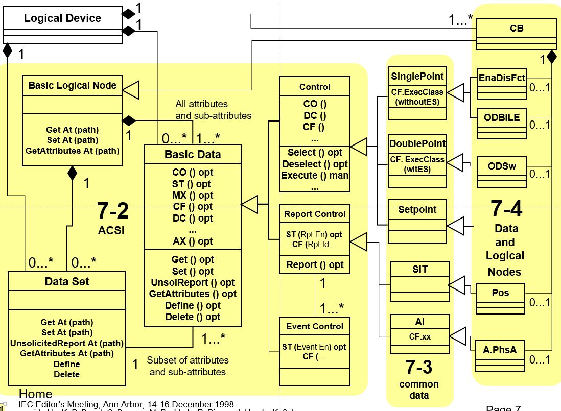
The experts involved have discussed several options how to model the signals. In December 1998 the editors of the core documents (including myself) met in Ann Arbor (MI, USA).


We discussed modelling with ASN.1 or our own notation:


we were not quite happy ... then we discussed trying UML … walked across the street to the University bookshop to purchase some 10 Books about UML Modelling. I purchased several books, too:


… a senior development manager of protection relays was strictly against UML … he said, it will never be used for protection and automation. Some weeks later I met his engineers in their office … and saw that they used UML for developments …

Later I tried OWL with some success:


Experts involved in CIM (Common Information Models) used UML - with the SPARX tool Enterprise Architect (EA). It took several years before UML (and EA) was used to define all models of IEC 61850. Today (end of 2019) almost all models and other definitions are managed with the EA - it is a big success! The latest version comprises the following parts:


There are tools available to export parts of the model from EA as Word documents, html pages, pdf ...

Example of a model:


With the application of the SPARX EA we have a single source of all crucial definitions.

Note: The EA package "IEC61850Domain" is only available for the experts writing, publishing and maintaining the various standard parts.

Some exported documents (the so-called code components) are available for free access:
Click HERE for accessing these documents.

Thanks to the experts that have continuously pushed for using UML and EA. It took several years ... and it was not easy for engineers to use a formal language and tool to get where we are today.

These days the EA is used also for many other tasks: use cases, design state machines like for IEC 61850-90-16 (System management), ... IEC TC 57 has done a good job in using UML for CIM and IEC 61850. But another generation of engineers is needed to understand the full benefit of using UML.

Monday, October 8, 2018

IEC 61850-7-1 CDV Amendment 1 available for comments

The Amendment 1 of IEC 61850-7-1 is now available for comments and voting:

Communication networks and systems for power utility automation –
Part 7-1: Basic communication structure – Principles and models

IEC TC 57 just published the document 57/2035/CDV.

Ballot closes 2018-12-28.

The CDV is publicly available for comments for everybody:

Click HERE for Public CDV Commenting - you just need to register.

Please note the following:

The distributed CDV reflects the amendment 1 (corrections and extensions) to IEC 61850-7-1 Ed2.

A second document (called consolidated edition 2.1) incorporates the amendment 1 (120 pages) and the existing Ed2. The consolidated edition (195 pages) is circulated as 57/2036/INF (unfortunately not publicly available).
After the CDV/FDIS approval process the consolidated version will be published together with the amendment 1 under reference IEC 61850-7-1 Ed2.1.

The version 2.1 will introduce the latest modelling extensions.

The new version of IEC 61850-7-1 will be one of the most crucial documents of the standard series IEC 61850. As the editor of edition 1 I see that most of the content of the version 1 is still the basic information presented in this part 7-1 😊

This document shows also that the standard series is growing and getting quite complex ... for simple applications you need to understand what is mandatory and what is optional!

Saturday, December 24, 2016

DTR IEC 61850-7-500: How to use IEC 61850 for SAS

IEC TC 57 has published a Draft Technical Report (57/1817/DTR; 84 pages) with guidelines on how to apply IEC 61850 for substation automation:

Communication networks and systems for power utility automation –
Part 7-500: Basic information and communication structure – Use of logical nodes for modeling application functions and related concepts and guidelines for substations

Voting closes 2017-02-17

This is a document that you MUST read when you are involved in substation automation.

This Technical Report of IEC 61850 describes the use of the information model for devices and functions of IEC 61850 in applications in substation automation systems but it may be used as informative input also for the modeling of any other application domain. In particular, it describes the use of compatible logical node names and data objects names for communication between Intelligent Electronic Devices (IED) for use cases. This includes the relationship between Logical Nodes and Data Objects for the given use cases. ...
Part 7-5 describes in examples the use of logical nodes for modeling application functions and related concepts and guidelines in general independently from any application domain respectively valid for all application domains in the electric power system (substation automation, distributed energy resources, hydro power, wind power, etc.). This part 7-500 describes in examples the use of logical nodes for application functions in substation automation including also line protection between substations. It implies also some tutorial material where helpful. But it is recommended to read parts IEC 61850-5 and IEC 61850-7-1 in conjunction with IEC 61850-7-3 and IEC 61850-7-2 first.

Sunday, September 25, 2016

How to use Generic Input/Output Logical Node "GGIO"

The Logical Node Class GGIO (Generic Process I/O) is (in my experience) the most liked and hated Logical Node. Why? GGIO is often used instead of well known Logical Nodes.
Example: Use of GGIO0.ST.Ind1.stVal instead of XCBR0.ST.Pos.stVal
The use of GGIO is not standardized!
You may use it or not ... one way or the other.
Last week I was contacted by an utility engineer on how to map reporting signals (M1-Boolean, M2-Boolean, M3- ...)?
There are two general approaches in the use of GGIO:

1. Add semantic to Prefix of LN and use many GGIO instances (M1_GGIO1, ...)
2. Add semantic to extended Data Objects in GGIO (M1, ...)


In the first case we instantiate GGIO 10 times.
In the second we extend the model by defining Data Objects M1 ... M10

The main difference is that in the second example we can use the prefix of the GGIO ("Report_") -> "Report_GGIO0" as a wrapper for Reporting. The semantic of the signals is further defined by extended Data Objects "M1", "M2", ...
Both modelling approaches are defined in IEC 61850-7-1 and 7-4. The second approach may not be supported by all tools and devices.
I personally would prefer the second approach.

Monday, August 17, 2015

What is an IEC 61850 Data Model – Come and See

Data or device modeling is a crucial feature of IEC 61850 and IEC 61400-25. You may have seen many different approaches to explain how such a model looks like. Some five years ago I used these Russian dolls (matryoshka doll):

image

An IED contains a lot of “inner” objects.

[IMG_5083[3].jpg] 

Today I have thought that another approach may help you to understand the IEC 61850 approach:

image

What do you think? This and more will be explained in detail during my comprehensive – most liked – courses.

Friday, March 27, 2015

Out-Of-Range Quality Flag and Reporting Quality-Change Event

In addition to the following two discussions that contain a view on measured values:

What Does Complexity of a Protocol Mean-
Are you prepared for the Solar Eclipse 2015 on March 20-

I will now look into the possibility to automatically monitor and report the limit violation of a measured value using standard configuration of IEC 61850 Information Models (LN STMP1), Data Sets and Report Control.

There are two options to report the temperature value reaching the maximum possible value: using the quality information of the “Tmp.q” (configured by the configuration of the “max” value in “rangeC”) or the “Alm” (configured by “TmpAlmSpt”) as depicted in the following figure:

Idee_20150327_091258_01

We need to configure a Data Set and a Report Control Block for each case. In case of using “q” we have to communicate and interpret the “q” value “questionable and out of range” (which is a bit pattern!). In case of using the alarm data object “Alm” we just send and receive a simple Boolean value “True”. There is no need to interpret a bit pattern.

For machines it should be no big difference to analyze a bit pattern or a Boolean value.

Both approaches would provide the information that a measured value is higher than a specific limit (max or alarm limit). Which one you would like is up to you.

It is recommended that for specific domains it is specified in a “profile” document, which option to use. Maybe you want to use both: the “q” for asset management and the “Alm” for Automation functions to automatically start a cooling system. The “Alm” could easily be used for GOOSE messaging to inform a wide range of subscribers of the alarm …

The nice thing is that you can easily configure the multiple options just by SCL !! No programming needed – if the values of “q” and “Alm” are provided by the application.

Lesson learned: First define your need – then design the behavior of your Report and GOOSE messaging. If you don’t know what you want to accomplish, no standard can help you.

Saturday, February 14, 2015

VHPready Signal MMXU1.TotW.instMag – versus IOA 113

Signals configured in IEC 61850 and configured in IEC 60870-5-104 look quite different.

The following figure shows the same signal (Current electric Power – Aktuell erzeugte elektrische Leistung) in IEC 61850 (left) and IEC 60870-5-104 (right):

image

The IEC 61850 model exposes the value, quaity and timestamp as well as the semantic (TotalWatt). The total watt of what? Of the “Current electric Power – Aktuell erzeigte elektrische Leistung” as described in the DC (description of the signal).

On the other side we have the information object address (IOA = 113) that carries the same value in IEC 60870-5-104. What does the value 3456 mean? No idea in IEC 60870-5-104. You have to know upfront what 113 means. IEC 61850 stores the meaning in the device (model).

In the above case we see also the IOA=113 in the description (DC) of the IEC 61850 model. It is a text string attached to the DC attribute.

Monday, February 9, 2015

IEC 61850 Series is Growing to a Total of 45 Parts

IEC 61850 (Communication networks and systems for power utility automation) is a unique standards series providing a consistent set of standards, draft standards and other IEC publications.

A total of 45 parts cover many application domains in the Power Delivery System. An additional five (5) parts are published under the number IEC 61400-25 (extensions of IEC 61850 for Wind Power).

Document types of IEC:
IS = Standard
TR = Technical Report
TS = Technical Specification

21 Parts are already officially published. 24 draft parts are under preparation. Several drafts will be officially published in 2015.

The list of all documents:

image image image

In order to keep the crucial contents (mainly models and services) of these parts consistent, IEC TC 57 WG 10, 17, and 18 have done a tremendous work in converting the crucial contents into UML documents. This allows to extend and maintain the models with support of tools. In future we will see standard documents automatically derived from the UML Models.

Congratulation to all people contributing to this great standard series IEC 61850!

Some 20 years after the IEC TC 57 has decided (in 1995) to write a new standard for substation protection and automation, we see a lot of interest in many different application domains.

In case you need help to understand the many different parts and how they could contribute to solve needs you are faced with today and tomorrow – let me know please.

Even IEC 61850 is a huge Standard Series – it must be accompanied by REAL APPLICATIONS and underlying network infrastructure. The 7 ISO/OSI layers are just a foundation for IEC 61850 – both together are used by applications:

image

The applications of IEC 61850 can range from a simple polling of a temperature measurement up to comprehensive Schedules to manage distributed energy resources.

By the way: Te cake was very tasty!

Thursday, July 18, 2013

IEC 61850 – How to use the Standard in Substations?

The German mirror committee of IEC TC 57 (DKE K 952) is quite active in supporting IEC 61850 and helping the utility industry to discuss the application of IEC 61850 and provide feedback to the international standardization. Congratulation to all experts that have contributed to that work for many years! Well done!
The final documents of the modeling and engineering group provide a great inside view into the many use cases of IEC 61850 in protection and substation automation. The crucial results are written in English, too. Four out of seven topics are published in English:
  1. Überblick [DE] / Overview [EN]
  2. Engineeringprozess [DE] / Engineering Process [EN]
  3. Engineeringwerkzeuge [DE]
  4. Modellierungsrichtlinie [DE] / Modeling Guide [EN]
  5. Mustermodellierung [DE]
  6. Applikationsbeschreibungen [DE] / Application Description [EN]
  7. Weitere Applikationen [DE]
Click HERE to access the above documents. The pdf documents are free to download.
Enjoy.

Friday, December 28, 2012

IEC 61400-25 is based on IEC 61850

During the year 2012 I have received more often the question about the relation between IEC 61400-25 and IEC 61850.

The most crucial issue in understanding IEC 61400-25 is this: The standard series IEC 61400-25 is based on the series IEC 61850 (mainly part 7-x, 8-1). A lot of definitions and basics defined in IEC 61850 are not repeated in IEC 61400-25. The part 6 (Configuration language) is not referenced in IEC 61400-25 at all and so on.

Could part IEC 61850-6 be used for IEC 61400-25? Yes, it could be used in almost all implementations of IEC 61400-25. Why? Because usually the implementation of the communication uses the mapping to MMS according to IEC 61850-8-1 which is referenced in IEC 61400-25-4.

To really understand IEC 61400-25, one needs to have a very good basic understanding of IEC 61850.

The standard IEC 61850 could be understood as extended IEC 61850 information models. There are a few special definitions in IEC 61400-25-2 which deviate partly from IEC 61850-7-3 and 7-4.

Example: LN WGEN – Generator

That model comprises among other data objects the objects for 3 phase currents and voltages for the stator and for the rotor:

image

The argument why the electrical measurements are contained in the LN WGEN is simple: The Generator generates voltages and currents … so these measurements are an integral part of the generator! Full stop. In IEC 68150 the modeling approach is to find the smallest parts of information to be exchanged by a function to be modeled.

The electrical measurements in IEC 61850-7-4 are contained in the LN MMXU. To indicate the use for the stator or rotor could be indicated by a prefix in the instance name: Sta_MMXU.A and Rtr_MMXU.A.

image

Note how the instance names are build (according to IEC 61850-7-2 Edition 2):

image 
 
During the ongoing maintenance work on the first five parts of IEC 61400-25 it could be expected that the information models of IEC 61400-25-2 and IEC 61850-7-x will be harmonized as much as possible.

Note that the models may be different – there may be two model, but there is only one real world. The real world does not change depending on models! On the other side, models should be harmonized to a high degree … to prevent confusion. I have seen models implemented for a wind turbine that use MMXU instead of the models in WTUR.

The key issue is: different people and groups have different understanding of modeling!