Tuesday, April 28, 2015

The Complete Content of the IEC 61850 News Blog is now Available as Single PDF Document

For those readers of this IEC 61850, IEC 60870-5/6, DNP3, … news blog that want to get the complete content as a single pdf document, it is just a click away … it contains 1000+ posts from 2008 until 2015-04-28. Once you have downloaded the file you can easily browse the content … search … mark … copy … You will find useful information about the standards, vendors like ABB, HMS, Siemens, or utilities …

Click HERE to download all posts of the IEC 61850 blog in a single pdf [11.3 MB, 766 pages DIN A4]

Enjoy.

In case you have a question, drop us an EMAIL.

OPC Server using an IEC 61850 Client

OPC (DA and UA) is used quite often for higher level communication between PLCs and SCADA servers. How could you tap IEC 61850 information for communication to an OPC Client?

First of all, you need an IEC 61850 Client that talks to IEC 61850 Servers or receives GOOSE messages. Second, you need an OPC Server that sits on top of the IEC 61850 Client.

Softing (Nuremberg/Munich, Germany) offers such an OPC (DA and UA) Server with an IEC 61850 build-in client. The client automatically detects all logical nodes and data objects and converts them automatically into OPC items:

 image

OPC Server (DA and UA, dataFEED OPC Suite) with the build-in IEC 61850 client as well an OPC demo client from Softing is available, contact: http://industrial.softing.com/en

A free of charge copy of the dataFEED OPC Suite and OPC Client is available for interested attendees of NettedAutomations training courses.

Click HERE to check a Video with a brief demo on how to use the dataFEED in conjunction with IEC 61850.

What is “Control with Enhanced Security”?

The IEC 61850-7-2 Control Model defines several operation modes:

  • Status Only
  • Direct control
    - normal security: Operate, TimeActivatedOperate, Cancel
    - enhanced security: Operate, TimeActivatedOperate, Cancel, CommandTermination
  • SBO control (Select Before Operate)
    - normal security: Select, Operate, TimeActivatedOperate, Cancel
    - enhanced security: SelectWithValue, Operate, TimeActivatedOperate, Cancel, 
       CommandTermination

Have you ever tried to understand, implement, or use the option “Control with enhanced security”? The term can be quite misleading for people to believe that it has something to do with Cyber Security! No, it is not linked to that kind of security – even every operate command shall be secured by communication security measures.

So, what is it then? Usually I have explained it with the following slide.

image

Here is a one of many understandable use-cases for a specific switchgear (based on an email exchange with a very good friend of mine – a real switchgear expert … that believes in IEC 61850):

The proper name should be “Control with Confirmed Feedback”, so that any interlocks in the switchgear (can be abstract as well), need to be in the De-active state for the switchgear to report “Command Termination”, which would mean: the Control Element is now ready for another Operate service request.

A circuit breaker (CB) spring (drive) mechanism may work that it is only charged when the CB is Opened or Tripped. Then the energy in the spring mechanism would be enough to perform a Close Operation as well as a Trip Operation.

As the Trip mechanism does not need spring re-charging, it is instantaneous. However, there is a big delay after the Trip operation which is needed for the spring to charge or reset the mechanism again.

Although the indication of Trip will be instantaneous and reported spontaneously, however the switchgear cannot accept a new command since the spring mechanism is being recharged. During this time, the unit will not transmit the ‘Command Termination’ message so that a new command cannot be initiated. Once the spring is successfully charged, a ‘Command Termination’ message is transferred.

The CB mechanism example given above is one of many… there are some linear actuators which can Over-shoot during the process of operating the switch, this is then re-adjusted (i.e., brought to the normal position) after the instantaneous status change. The extra time needed to re-align actuator position (or to bring the actuator in the dead zone), will be the time after which the ‘command termination’ message is sent out.

Lesson learned: Ask always the domain experts!

Any question on IEC 61850?

Draft IEC 61850-8-2 SCSM – Mapping to XER and XMPP

Some 20 years after the first draft IEC 61850-8-2 SCSM (Mapping to Profibus FMS) we could expect the real IEC 61850-8-2 to be available by end of 2015.

The draft 8-2 provides an additional mapping of the messages of MMS by XER (XML Encoding Rule) and XMPP.

The MMS messages for IEC 61850-8-2 (above TCP/TLS/XMPP) are just differently encoded as in IEC 61850-8-1, as can be seen by the following example:

image

ASN.1 BER uses a binary encoding that produces less overhead compared to XER. But there will be many benefits provided by IEC 61850-8-2.

According to a presentation by Siemens during the Hanover Fair 2015, these are the main conclusions:

  1. It provides a secure and powerful communication for public networks considering end-to-middle and end-to-end security relations
  2. IEC 61850-8-2 is intended to use for power management and demand response of DER (distributed energy resources)
  3. In 2015 the IEC TC57 working group WG17 will finalize and publish this new specification

Click HERE for the full presentation [pdf, 3 MB]

Sunday, April 19, 2015

Attacks doubled on SCADA systems

According to a recent Dell Report the security of SCADA systems is very poor:

“Industrial operations often use SCADA systems to control remote equipment and collect data on that equipment’s performance. Whereas the motive behind POS and secure web browser attacks is typically financial, SCADA attacks tend to be political in nature, since they target operational capabilities within power plants, factories, and refineries, rather than credit card information. In 2014, Dell saw a 2X increase in SCADA attacks compared with 2013.

We saw worldwide SCADA attacks increase from 91,676 in January 2012 to 163,228 in January 2013, and 675,186 in January 2014.

The majority of these attacks targeted Finland, the United Kingdom, and the United States, likely because SCADA systems are more common in these regions and more likely to be connected to the Internet. In 2014, Dell saw 202,322 SCADA attacks in Finland, 69,656 in the UK, and 51,258 in the US.”

Click HERE for the full Dell Security, Annual 2015 Threat Report

It MUST be mandatory to implement and use measures as defined, e.g., in IEC 62351!!

Yes, it costs money – but it may cheaper to spent the money now and not later when the damages happen.

Don’t accept excuses.

Monday, April 13, 2015

Background and Personal Experience of Karlheinz Schwarz

Do you need help regarding IEC 61850, IEC 61400-25, IEC 60870-5-104, DNP3, IEC 62351 (Security), CIM, IEC 61158 (Fieldbus), Modbus, …

Click HERE for a description of personal experiences, capabilities, ... find an introduction on IEC 61850, list of training modules, feedback from attendees, list of courses, countries, and pictures (updated 2015-04-11) [pdf, 4.3 MB]

Saturday, April 11, 2015

IEC 61850 at the Hannover Messe 2015

Products and Services regarding IEC 61850, IEC 60870-5-104 and other standards can be seen in action, e.g., at these booths:

SystemCorp, Perth, Australia
Booth C35/4 in Hall 13

Click HERE for details and a free entrance Ticket.

Beck IPC, Wetzlar, Germany
Booth C35/5 in Hall 13

Click HERE  for details and a free entrance ticket.

HMS Industrial Networks, Halmstad, Sweden
Booth D35 in Hall 8

Clicke HERE for details and a free entrance ticket.

IEC 61850 Seminar und Training: Erfolgreiche Serie in Deutsch wird auch 2015/2016 weitergeführt

Die erfolgreiche Serie von IEC 61850-Seminaren und Hands-On-Training-Kursen in deutscher Sprache wird auch in diesem und nächsten Jahr weitergeführt. Die drei ersten Termine in Karlsruhe wurden von insgesamt 28 Teilnehmern aus Deutschland wahrgenommen! Das Interesse an kostengünstiger Ausbildung in Bezug auf Normen wie IEC 61850, IEC 61400-25 oder IEC 60870-5-104 ist mittlerweile groß!

NettedAutomation bietet weitere drei Termine für das dreitägige Seminar und Training in Karlsruhe an:

26.-28. Oktober 2015
11.-13. Januar 2016
14.-16. März 2016

In über 200 Seminaren und mit mehr als 3.800 Teilnehmern aus über 900 Firmen und über 80 Ländern geschult ... und ist damit die erfolgreichste herstellerunabhängige Schulung und Training in Deutsch und Englisch!

Anlässlich der Hannover Messe 2015 bieten wir für die dreitägige Schulung einen nahezu

unschlagbaren Sonderpreis von 790 Euro

an!

Kicken Sie HIER für weitere Details wie Programm, Schulungsort und Anmeldeformular.

Weitere Seminare (beispielsweise speziell für Schutzingenieure) finden Sie HIER.

Personal experience, capabilities, of Karlheinz Schwarz ... introduction on IEC 61850, training modules, feedback from attendees, list of courses, countries, and pictures
(updated 2015-04-11) [pdf, 4.3 MB]

Thursday, April 9, 2015

Will Information Networks become the “Backbone” of the Power System?

Information sharing between any kind of intelligent devices is a crucial need for today’s an the future Power Delivery Systems. It requires a huge infrastructure to send information back and forth.

Who do you think will put a lot of efforts into the infrastructure to get control over the information to be shared? Will protection engineers or mechanical engineers (e.g., of wind turbines) gain control over the information infrastructure? I guess that it will work the other way around: The specialists of network infrastructure will have a big impact on how the information will be shared in future.

One of the many activities is supported by a special group within the IETF (Internet Engineering Task Force): Energy Management (EMAN)

Excerpt from the current Applicability Statement

Abstract

The objective of Energy Management (EMAN) is to provide an energy management framework for networked devices. This document presents the applicability of the EMAN information model in a variety of scenarios with cases and target devices. These use cases are useful for identifying requirements for the framework and MIBs.

1. Introduction

The focus of the Energy Management (EMAN) framework is energy monitoring and management of energy objects [RFC7326]. The scope of devices considered are network equipment and their components, and devices connected directly or indirectly to the network. The EMAN framework enables monitoring of heterogeneous devices to report their energy consumption and, if permissible, control. There are multiple scenarios where this is desirable, particularly considering the increased importance of limiting consumption of finite energy resources and reducing operational expenses.”

Click HERE for the current “Energy Management (EMAN) Applicability Statement, draft-ietf-eman-applicability-statement-10”

From an information sharing point of view there is no difference between information of a router or Ethernet Switch and a protection, monitoring or control IED (Intelligent Electronic Device) in the sense of a Fieldbus, DNP3, IEC 60870-5-104 and IEC 61850.

Finally IETF could play a major role in the world of networked devices – including everything that is believed today as somehow special: Field devices on one of the hundreds of fieldbusses, IEDs in the Power delivery systems, etc.

If you are looking for a unique (single standard) that is accepted and used all over the globe: It is IEC 61850. Use the ORIGINAL. A mapping of the IEC 61850 objects (IEC 61850 Logical Nodes and DataObjects) onto a MIB and SNMP could make sense – especially when the structures are used unchanged. The same is true for a mapping of specific MIBs for Ethernet Switches and Routers. This is already happening in IEC 61850-7-4 Ed2 for some network related information, e.g., in:

LN LCCH: Physical communication channel supervision:

image

More to come.

The motto of NettedAutomation GmbH since 2000 is: “The Net is The Automation”.

Wednesday, April 8, 2015

Can Power Outages impact the application of IEC 61850?

Yes – it can. Why? More often we receive reports on power outages caused by aging components of the grid. Upgrading many aged insulators, transformers, lines, … costs a lot of money! This money is not available for new technologies! Yes!

Yesterday it was an insulator that broke. The 220 kV line dropped to the ground and caused a blackout in the Washington (DC) and other areas. They were surprised that they “did not know why the outage rippled to far from the Ryceville switching station.”

Click HERE for a news message on yesterdays event at Ryceville switching station.

A similar incident happened back to 2009 in Auckland, New Zealand, which had a direct impact on IEC 61850 applications. Excerpt from a report on February 13, 2009:

“A power lines company is getting flak from the government after one of its conductors collapsed on to houses, trapping people in south Auckland. Amazingly, no-one was hurt when Transpower's monster 220,000 volt line came crashing down late on Friday morning.

The incident comes just 10 days after a Transpower transformer failed and plunged 75,000 Auckland residents and businesses into darkness for two hours.
"It's just totally unacceptable," says John Key, Prime Minister. "So look, there is going to be a massive expenditure on the upgrading of Transpower's grid and I'm making sure that that network is not only more reliable, but safer," he says.
Transpower is investigating the latest incident and feeling the political heat. "It's fallen into a residential area that's been built under the lines since the line was constructed in the fifties and sixties. But no, it's not good enough," says Kieran Devine, Transpower operations manager.”

Click HERE for the (old) news on the Transpower incident.

The Transpower incident had a direct influence on a project to get experience with IEC 61850 in substations. The project was stopped and my consultancy contract with Transpower was canceled soon after the incident happened.

The aging infrastructure is about to “eat” a good part of the funding for new technologies … including implementation of cyber-security measures. So it is no surprise that in some cases in the U.S we see routable protocols being replaced by serial links! This saves a lot of dollars.

Excerpt from a GarretCom paper on non-routable protocols:

“… When only non-routable protocols are used, substations with critical assets are networked
without requiring the use of Critical Cyber Assets (CCAs) at remote substations, as defined in CIPstandard CIP-002. Avoidance of “CCAs” means that the other CIP-002 to CIP-009 requirements do not
apply at these substations, which will likely defer significant implementation costs and ongoing
administrative overhead associated with CIP compliance
.”

Click HERE for the complete report. See also HERE or HERE for more details on the NERC CIP on non-routable protocols.

Tuesday, April 7, 2015

Secure Power Delivery Systems and Secure Communication

The power utility domain is facing a lot of challenges these days. There are environmental, technical, political, security-related, and market-related issues that require a new design of the whole chain of design, procurement, installation, operation and maintenance of systems that are needed to provide the needed power to the users of power.

There are tons of lists that require this and that. Take the cyber security aspect: You will find many documents that could help you to procure the right solution. One of the latest documents provides helpful text to write down the needs for “Cyber security of Power Delivery Systems”:

“Cybersecurity Procurement Language for Energy Delivery Systems”

Written by US-Experts and published last year.

Click HERE for a copy.

Many (likely most) publications on securing our infrastructure are assuming a mainly hierarchical and centralized Power Delivery and Automation Systems as described in the following (excerpt from the above document, page 1):

“Energy delivery systems comprise the following:

  • The sensors and actuators used for monitoring and controlling energy delivery processes.
  • The computer-based systems that analyze and store data.
  • The communication pathways and networks that interconnect the various computer systems.

Cybersecurity threats, whether malicious or unintentional, pose a serious and ongoing challenge for the energy sector. Today’s highly reliable and flexible energy infrastructure depends on the ability of energy delivery systems to provide timely, accurate information to system operators and automated control over a large, dispersed network of assets and components.

The cyber security requirements could be lowered dramatically in case we think of a more de-centralized Power System that would need a de-centralized Automation System over a small local system of assets and components – requiring a minimum of operational communication with the next hierarchy level.

It seems to be in the interest of manufacturers of network infrastructure to implement huge systems to control a large, dispersed network of assets and components. Sure: This would require a huge, secure network infrastructure – a huge and long-term business case. Cyber-Security seems to be a new support programme to the vendors of communication and automation infrastructure.

As we have experienced, more or less (intended!) simultaneous control commands to a huge number of assets could danger the stability of the power network. I guess that the risk in using a highly cyber-secure network (for monitoring and control) in a large hierarchical power system is much bigger than the risk of a “less” secure network (for monitoring and control) in small de-centralized, self-organizing power systems.

A cyber-secure network is one issue – the (physical and technical!) architecture of our future Power Delivery System is another.

Why don’t we pay more attention to distributed Power Delivery Systems that require distributed monitoring and control? Exchanging measurements, status, settings, and control commands in a huge hierarchical automation system will always be compromised by some people.

Would you trust an avalanche of measurements and status points arriving from millions of sensors communicated in a second? Would you trust that a setting going to millions of controllers will be interpreted in the same way? Or what’s about a control commands send out to ALL actuators? The un-thinkable is already a reality. It happened already last year in Bavaria and Austria.

I experienced the mis-interpretation of the power of my green laser pointer when I went through security of an international airport. My pointer has a power of “<1mW”. I was near to be arrested because the police officer was reading “one MegaWatt” … Fortunately I could help to translate “m” to “Milli”. Finally I had to check-in the pointer before I could go onboard.

I guess that one of the biggest challenges is to find an architecture of our future power delivery system that requires just a few or no measurements, status, settings, and control commands being exchanged between millions of interconnected intelligent devices and systems.

Tuesday, March 31, 2015

IEC 61850-9-2 Sampled Values In Use

Quite often people ask me about the application of sampled values according to IEC 61850-9-2 (9-2LE). The sampled values require very solid products (publisher, Ethernet Switches, and subscribers). The recent years have shown that the technology has matured to an extend that applications are already available or underway.

Please find useful links:

Click HERE for the paper:

Test and Evaluation of Non Conventional Instrument
Transformers and Sampled Value Process Bus on Powerlink’s
Transmission Network

Click HERE for a related publication:

Australia Leads With Process Bus

Click HERE for the 9-2LE guideline published by the IEC 61850 community.

More and more 9-2LE compliant IEDs are tested and certified.

There are more than 400 IEDs (Server, clients, publisher) that have been certified by the UCAIug:

image

Source: UCAIug

What’s about subscriber to sampled values?

Click HERE for various protection IEDs implementing the subscriber role for sampled values, e.g., Alstom Distance Protection Relay P446, …

More to come.

IEC 61850-9-3: Precision Time Protocol Profile for Power Utility Automation

IEC TC 57 has published the other day:

IEC/PAS 61850-9-3 (57/1551/PAS):
Communication Networks and Systems for Power Utility Automation –
Part 9-3: Precision Time Protocol Profile for Power Utility Automation

Voting terminates on 2015-05-01

The intent of this publication is to present a widely agreed technical solution for a precision time protocol (PTP) profile of IEC 61588:2009 applicable to power utility automation. There is urgent need in the power industry for a appropriate profile for power automation application to be defined in IEC 61588. This PAS (Public Available Specification) is intended to temporarily be used as a reference.

This allows to meet the highest synchronization classes of 108 IEC 61850-5 and IEC 61869-9.

IEC 62351-9: Cyber Security Key Management for Power System Equipment

IEC TC 57 has published the following draft standard:

IEC 62351-9 Ed.1 (57/1565/CD):
Power systems management and associated information exchange – Data and communications security – Part 9: Cyber security key management for power system equipment

Closing date for comments is 2015-07-03.

IEC 62351-9 specifies how to generate, distribute, revoke, and handle digital certificates and cryptographic keys to protect digital data and its communication. Included in the scope is the handling of asymmetric keys (e.g. private keys and X.509 certificates), as well as symmetric keys (e.g. session keys).
This part assumes that other standards have already chosen the type of keys and cryptography that will be utilized, since the cryptography algorithms and key materials chosen will be typically mandated by an organization’s own local security policies and by the need to be compliant with other international standards. This document therefore specifies only the management techniques for these selected key and cryptography infrastructures. The objective is to define requirements and technologies to achieve interoperability of key management.

Data and communications security are very crucial for the future power delivery system – take the various documents of the series IEC 62351 very serious!

Friday, March 27, 2015

How to Migrate to Internet Protocol Version 6 (IPv6)?

IEC TC 57 just published a new draft document for a future Technical Report:

IEC 62357-200 TR (57/1563/DTR):
Power systems management and associated information exchange –
Part 200: Guidelines for migration to Internet Protocol version 6 (IPv6)

Application: Utility communications using utility-owned and leased networks, including, but not restricted to communication within substations, from substation to substation, from substation to control center / maintenance center, control center to control center, energy management systems, synchrophasors, distributed and bulk energy generation and storage resources and (including fossil fuel plants and renewables) wind-, and solar power generation, storage, demand side management, and demand response for distribution level consumers / producers.

This draft Technical Report addresses the issues encountered when migrating from Internet Protocol version 4 (IPv4) to the Internet Protocol version 6 (IPv6). It describes migration strategies, covering impact on applications, communication stack, network elements, configuration, address allocation, cyber security, and the related management.

The migration will add new need and require more skills of the engineers. It is highly recommended to have some people that start learning the changes that will come during the next 30+ years.

Maybe you start with a small group as we did in the standardization process 15+ years ago in Seattle (WA) in 1999:

CB_1_2

Teamwork makes the dream work!

Be aware that the “network infrastructure” becomes one of the most crucial basics for all other infrastructures.

Would your company’s communications infrastructure survive a blackout like the one in The Netherlands today (2015-03-27)?

“Dutch electricity network administrator Tennet says that a large part of North Holland province, which is home to some 2.7 million people, was hit by the outage.

Tennet said on its Twitter feed that the outage was caused by a “technical fault” a high-voltage power station in the town of Diemen, just outside Amsterdam.”

Source: The Independent

I hope it was not caused by an “unknown” GOOSE Trip Message! … Which – at least – would mean it was not related to TCP/IP … IPv4 or IPv6. I am kidding! … a bit.

Out-Of-Range Quality Flag and Reporting Quality-Change Event

In addition to the following two discussions that contain a view on measured values:

What Does Complexity of a Protocol Mean-
Are you prepared for the Solar Eclipse 2015 on March 20-

I will now look into the possibility to automatically monitor and report the limit violation of a measured value using standard configuration of IEC 61850 Information Models (LN STMP1), Data Sets and Report Control.

There are two options to report the temperature value reaching the maximum possible value: using the quality information of the “Tmp.q” (configured by the configuration of the “max” value in “rangeC”) or the “Alm” (configured by “TmpAlmSpt”) as depicted in the following figure:

Idee_20150327_091258_01

We need to configure a Data Set and a Report Control Block for each case. In case of using “q” we have to communicate and interpret the “q” value “questionable and out of range” (which is a bit pattern!). In case of using the alarm data object “Alm” we just send and receive a simple Boolean value “True”. There is no need to interpret a bit pattern.

For machines it should be no big difference to analyze a bit pattern or a Boolean value.

Both approaches would provide the information that a measured value is higher than a specific limit (max or alarm limit). Which one you would like is up to you.

It is recommended that for specific domains it is specified in a “profile” document, which option to use. Maybe you want to use both: the “q” for asset management and the “Alm” for Automation functions to automatically start a cooling system. The “Alm” could easily be used for GOOSE messaging to inform a wide range of subscribers of the alarm …

The nice thing is that you can easily configure the multiple options just by SCL !! No programming needed – if the values of “q” and “Alm” are provided by the application.

Lesson learned: First define your need – then design the behavior of your Report and GOOSE messaging. If you don’t know what you want to accomplish, no standard can help you.

Friday, March 20, 2015

Germany Survived the Solar Eclipse 2015 on March 20

During the last days and months there were a lot of discussions and news about a possible blackout during the Solar Eclipse 2015 today. The operators (and the nature) were quite well prepared for the event.

Lesson 1 learned: Nature and Operators did a good job!

Is there another lesson learned? Sure!

Due to the fact that the universe is not made by human beings, we could predict the movement of the sun, the moon and the earth … and thanks to mathematics we could calculate the impact of the sun on a sunny day like today …

image

Source: ENTSO-E; click HERE for further details provided by ENTSO-E.

The first maximum of PV power feed-in of 13.3 GW was at 9:45 h today. One hour later the minimum feed-in was 5.1 GW at 10:45 h.

image

Source: SMA, click HERE for the online data (then select March 20, 2015).

Between 10:45 h and 11:45 h the feed-in grew by 11,7 GW. That means 195 MW per minute or 3,25 MW per second. The maximum of the day was 20.3 GW at 12:45 h.

image

Source: SMA, click HERE for the online data (then select March 20, 2015).

Note that the forecast was very accurate, as can be seen in the following diagram:

image

Source: TransnetBW; click HERE for the online data.

The forecast of March 13, 2015 (one week before) was some 700 MW higher than the actual value for 13:00 h, as can be seen in the following figure:

image

Source: TransnetBW; click HERE for the online data.

The transmission companies have spent a lot of money to get a very precise forecast for today – and it worked fine. But these efforts were taken because it was a remarkable day. The forecast may become better – they are still modeling the physical world with laws set by the creator of the nature. The future power system will be impacted by more man-made “laws” that focus more on profit than on physics.

How many power plants have been used today to control the frequency and balance the load and generation? Maybe a few hundred. These power plants are well equipped with remote terminal units and communicate through IEC 60870-5-101 (and some with -104).

The control center are able to control remotely in the context of schedules plant for the day.

Another question is: What if we have to control Millions of decentralized resources (in some years)? What if we have not only 40+ GW Wind Power and 50+ GW PV power installed?? Who will provide the needed schedules for millions of feed-in points? Who and how will we control millions of these resources?

And how will we guarantee that the needed communication links between millions of intelligent devices will operate in a disaster situation? Note: TODAYs Solar Eclipse was far away from a disaster!

And what happens if somebody manipulates the information and information exchange? Even if we limit the active control commands to a very few or forbid them at all. We need to exchange at least situational information: current, frequency, voltage, power factor, or … Who guarantees that the values exchanged can be trusted?

Can we then trust that we know all communication connections that end in a power plant? You would be surprised if you would start to list the communication assets. As an expert recently said: “I have had the same experience as … with respect to finding "unknown" remote access connectivity at almost every facility I have assessed. These include dial-up modems, wireless access points, and network interface cards that IT and Corporate Engineering did not know existed.” Somebody else said: “At another facility we were told that external connections were always unplugged, but we were able to call the equipment at the phone number we saw posted.”

The future of our power delivery system is dependent on millions (instead of hundreds) of power resources, and on human beings that may loose the control over the communication infrastructure or that may compromise the communication and control systems.

Lesson 2 (to be learned by all): Take the communication, secure communication, control, secure control, impact of the physics on the power system and other aspects MORE SERIOUS! Think always how to apply standards – I mean real standards like IEC 60870-5-104, IEC 61400-25, IEC 61850, or DNP3.

There is a lot to be accomplished at the engineering level! Power is more than Euros and Dollars … let’s do the job together. We need you all.

All people that have read to this end will agree with me (at least in general).

Thanks for taking your (spare!?) time.

Wednesday, March 11, 2015

What Does Complexity of a Protocol Mean?

There is always a discussion on one protocol being more efficient and less complex than another or all other. Does this discussion help? I don’t think so.

The key issue is the “SYSTEM” – which is MUCH more than a protocol.

Let’s discuss briefly the configuration of a device with regard to reporting a value based on a deadband configuration and the range and multiplier of an analog value.

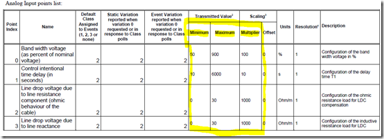
Usually the deadband values and range configurations and other crucial information are specified in a pdf file or – if you are lucky – in an excel sheet or XML file. So, to interpret a message the receiver has to know the configuration. The tables contained in the pdf file (below) have to be translated by somebody manually … and how can I find out in 10 years from now, what the limits of the Band width voltage are? Hm. No idea?! Usually you cannot ask the device. So, what now?

I am sorry, if you don’t have the pdf you may guess what the limits are – but you don’t know. Maybe somebody from the vendor is still there and can answer the question.

Example of a DNP3 SPECIFICATION - DEVICE PROFILE

Excerpt on deadbands and configuration:

image

image

A good thing is, that many vendors publish these files. Sur, you never know if they are up-to-date or applicable for your device you installed some time ago.

The information models of IEC 61850 provide dedicated attributes for a value that provide these meta data like deadband configuration, min, max, multiplier, SIUnit. These attributes could be used in the corresponding SCL file only or they could additionally be exposed by the device and made accessible through a simple read message.

With IEC 61850 in place we could easily expose the limits of power production and load and further attributes. The logical node MMXU (IEC 61850-7-4) could be used for the limits in which a value is valid:

Data Object TotW of class MV (measured value, IEC 61850-7-3) - Total active power (total P)

could provide the actual value, quality, range, Scale, limits, units, deadband in the details provided through the MV CDC:

mag.f deadband filtered AnalogueValue coded as floating point
q Quality
range ENUMERATED normal|high|low|high-high|low-low (out of range would change quality value)
rangeC RangeConfig:
hhLim
hLim
lLim
llLim
min
max
sVC ScaledValueConfig (scale and offset) for Integer values
db Deadband filter in % of range (min – max)
units SIUnit and multiplier

min: the min (minimum) attribute shall represent the minimum process measurement for which values of i or f are considered within process limits. If the value is lower, q shall be set accordingly (validity = questionable, detailQual = outOfRange).

max: the max (maximum) attribute shall represent the maximum process measurement for which values of i or f are considered within process limits. If the value is higher, q shall be set accordingly (validity = questionable, detailQual = outOfRange).

In our case, the TotW for the CHP generator may be limited between 0 W (min) and 35 kW (max). A value of “minus 600” MW would have to be flagged as questionable and outOfRange !! Negative values and values higher than 35 kW would be flagged out of range!

The receiver (a control center) could check the limits of the values (either by reading the range configuration online by a service or getting it from the corresponding SCL file). It could figure out that the range is 0-35 kW. Even if the gateway (RTU) would send “minus 600” MW (load) … the CC could understand that this is a bad value – recommended not to use.

The ScaledValueConfig exposes the scale factor and offset value – required to interpret an integer value.

The deadband db defines when to report a new value: when a change of the value is “+/- db of the range”: a range of 100 A and db=2000 (2 %) means –> every change of 2 A will be reported; the last reported value was 78 A, then the next report will be issued when the value reaches 76 A or 80 A.

The units contain the SIUnit (e.g., A) and the multiplier (10**0 –> 1).

The meta-data of the measured value serve as a means to help interpreting the plausibility and validation of a value communicated.

To focus on a message “Report a changed value based on a deadband configuration” and discuss which protocol does it more efficient is not helpful! Modbus can communicate the total Power – as can any other protocol. But: HOW to INTERPRET a received value? Is the value within the limits defined for an application? Is the value given in W, kW, MW or GW??

A system should be able to provide more than just A value – all crucial meta data that help to interpret the value are needed in any case. Either you get it – or …

Please focus on the “System” – a holistic approach is what we need.

This blog post will likely not stop protocol efficiency discussion … ok. And?

If it makes you happy when you discuss protocol issues … do it.