Showing posts with label IEC 61850-90-9. Show all posts

Thursday, November 18, 2021

Four Additional Light Namespace Documents For IEC 61850 Series Are Available For Free Access

 Please note that the following four namespace documents have been published the other day:


Click HERE to access these four and the other 22 name space documents.

  1. IEC 61850-90-9: Object models for electrical energy storage
  2. IEC 61850-90-4: Network engineering guidelines for substations
  3. IEC 61850-90-11: Methodologies for modelling of logics for IEC 61850 based applications
  4. IEC 61850-7-420: Communications systems for distributed energy resources (DER) - Logical nodes

Enjoy!

Monday, August 5, 2019

IEC Draft TR 61850-90-9 - "IEC 61850 for Electrical Energy Storage Systems" Published

IEC TC 57 just published the 138 page IEC Draft TR 61850-90-9

IEC 61850 for Electrical Energy Storage Systems

57/2128/DTR
Voting closes 2019-09-27

This is one of the next crucial extensions for DER-Models of IEC 61850-7-420. This TR will be merged into the 7-420 later on.

The Introduction states: " ...This technical report is primarily based on the recommendation 5.7.4. “interface, control and standard data elements”, of the IEC white paper ”Electrical Energy Storage” published in December 2011 by the MSB. The recommendation proposes the necessity of a standardization of interfaces between storage and other grid elements, protocols for data exchange and control rules, and data elements for input, output and control information supplied by or to storage systems. ..."

Click HERE for the mentioned IEC White Paper.

"This technical report describes IEC 61850 information model for electrical energy storage systems (EESS). Therefore the report only focuses on storage functionality in the purpose of grid integration of such systems at the DER unit level. Higher level Interactions are already covered in IEC 61850-7-420. ... "

The draft defines more than 150 new Data Objects. Excerpt of the first 15 Data Objects:


The blue marked text refers to the Logical Node from which this Data Object is inherited.

This document refers to the standards IEC 61850-7-x and defines additional very crucial information for the configuration, control, monitoring of a battery system.
It is very crucial for the success of the DER models to get implementation and application experience with these very comprehensive and complex models.
Taking into account that the mentioned White Paper was already published in 2011, we learn a crucial lesson: It took a lot of time to get where we are today. And it will take years to get these definitions implemented and used in the power delivery systems. In the mean time you need to tap the experience of engineers that understand the possible use-cases that can harvest the benefits of applying these standards.

Saturday, May 26, 2018

IEC 61850-90-9 - Use of IEC 61850 for Electrical Energy Storage Systems

IEC TC 57 has just published a 114 page new draft technical report:

57/1998/DC

Draft IEC TR 61850-90-9, Communication networks and systems for power utility automation – Part 90-9: Use of IEC 61850 for electrical energy storage systems

Comments are welcome until 2018-08-17

"This technical report provides necessary information within 61850 based object model in order to model functions of a battery based electrical energy storage system as a DER unit. For intelligently operated and/or automated grids, storing energy for optimising the grid operation is a core function. Therefore shorter periods of storing energy with charging and discharging capability is also an indispensable function. Charging and discharging operations need to be modelled thoroughly and are in the focus of this technical report. ...
An Electrical Energy Storage system (EESS) is a system which is used for the purpose of intermediate storage of electrical energy. The type of storage, the amount of energy, charging and discharging rates as well as self-discharge rate and many other characteristics are technology dependent and therefore can be very different. However, the general meaning of the characteristics and parameters are identical.
The objective of this document is to define a standardized and general approach to information
modelling for operating an EESS regardless of any specific technique, which supports an efficient way of integrating an EESS into grid operation and other businesses.
Various types of EESS, such as battery, pumped hydro, superconducting magnetic energy storage, flywheels, etc., are defined in “IEC White Paper on Electrical Energy Storage.” According to the the white paper, EESS systems are classified by energy form, advantages/disadvantages to the specific usages or the purpose of the implementation. ... "

Monday, August 7, 2017

IEC 61850-90-9 Models for Electrical Energy Storage Systems

IEC 61850 Part 90-9: Use of IEC 61850 for Electrical Energy Storage Systems is progressing these days. The latest draft describes the basic functions of Electric Energy Storage System (EESS) and the information model of the interface to integrate EESS in intelligent grids and establish the necessary communication with standardised data objects. The next official draft is expected to be published soon.
This draft  is  connected  with  IEC 61850-7-420,  as  well  as  IEC 61850-7-4:2010, explaining how the control system and other functions in a battery based electric energy storage unit utilizes logical nodes and information  exchange services  within the IEC 61850 framework to specify the information exchanged between functions as well as information that individual functions need and generate. The first Edition of IEC 61850-7-420 provides an information model for batteries which was derived from the proposed data objects of part 7-4. Those data objects follow the requirements of batteries that are supposed to be used in substations as an auxiliary power system and as backup power supplies. For this purpose it was sufficient to only model the discharge function. Therefore it is necessary to prepare new logical nodes to be applicable for grid connected electrical energy storage systems.
This draft provides necessary information within 61850 based object model in order to model functions of a battery based electrical energy storage system as a DER unit. For intelligently operated and/or automated grids, storing energy for optimising the grid operation is a core function. Therefore shorter periods of storing energy with charging and discharging capability is also an indispensable function. Charging and discharging operations need to be modelled thoroughly and are in the focus of this technical report.

The draft lists several use-cases found in the real world:

UC1 Retrieve current status and capabilities of EESS
UC2 Set charging power to EESS
UC3 Set discharging power to EESS
UC4 Set Operating mode/ schedule  to EESS
UC5 EESS Alarm / Asset Monitoring

UC1 current capability /status information as an example:

1-2-1 EESS Generic Status Reporting
•  ES-DER on or off
•  Storage available or not available
•  Inverter/converter active power output
•  Inverter/converter reactive output
•  Storage remaining capacity (% and/or kW)
•  Storage Free capacity (% and/or kW)

1-2-2 EESS inverter /converter status
•  Current connect mode:  connected or disconnected at its ECP
•  Inverter on, off, and/or in stand-by status: inverter is switched on (operating), off
(not able to operate), or in stand-by
•  mode, e.g. capable of operating but currently not operating
•  DC current level available for operation: there is sufficient current to operate
•  Value of the output power setpoint
•  Value of the output reactive power setpoint
•  Value of the power factor setpoint as angle (optional)
•  Value of the frequency setpoint (optional)

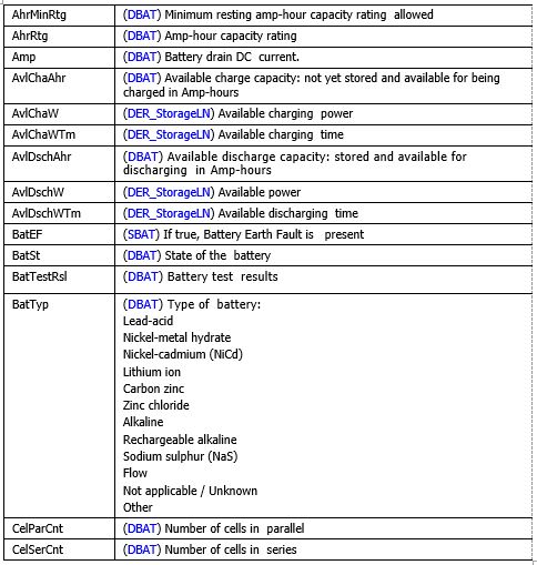
1-2-3 EESS (battery) internal status
 •  Amp-hour capacity rating
•  Nominal voltage of battery
•  Maximum battery discharge current
•  Maximum battery charge voltage
•  High and Low battery voltage alarm level
•  Rate of output battery voltage change
•  Internal battery voltage
•  Internal battery current
•  State of charge (energy % of maximum charge level)
•  Reserve (Minimum energy charge level allowed, % of maximum charge level)
•  Available Energy (State of charge – Reserve)
•  Type of battery

1-2-4 Power measurements
•  Total Active Power (Total P): Value, High and Low Limits
•  Total Reactive Power (Total Q): Value, High and Low Limits
•  Average Power factor (Total PF): Value, High and Low Limits, and averaging time
•  Phase to ground voltages (VL1ER, …): Value, High and Low Limits

More to come ...

Tuesday, December 2, 2014

Monitoring the Battery of the Boeing Dreamliner 787 would have helped to prevent damages

I guess you remember the trouble Boeing was faced with when the huge battery packs in the Dreamliner 787 some two years ago. The Auxiliary Power Unit Battery Fire was likely caused by several severe “cell internal short circuiting and the potential for thermal runaway of one or more battery cells, fire, explosion, and flammable electrolyte release”.

More precise Condition Monitoring would have helped to prevent such incidents – and would have shown very early that the design of the battery system was quite fragile.

One of the findings (page 91 of the released incident report) is:

“More accurate cell temperature measurements and enhanced temperature and voltage monitoring and recording could help ensure that excessive cell temperatures resulting from localized or other sources of heating could be detected and addressed in a timely manner to minimize cell damage.”

Click HERE for the complete official NTSB report.

Monitoring batteries is very crucial the more our life depends on these systems – in airplanes, in substations, power stations, mobile systems, communication infrastructure … It is not sufficient to have a battery – the batteries must be maintained, tested from time to time, and monitored continuously.

Two groups (I am aware of) have defined Battery Monitoring information models:

1. IEC 61850-90-9 (Use of IEC 61850 for Electrical Storage Systems)

Excerpt of the battery system (without further discussion):

image

2. IETF EMAN (Energy Management)

Definition of Managed Objects for Battery Monitoring / draft-ietf-eman-battery-mib-13

image

Click HERE for the EMAN draft for Battery Monitoring.

Battery monitoring could safe life!

Friday, January 11, 2013

Peak Load Shaving with Batteries – Isn’t that smart?

What does a power system make smart? Smart meters? Hm, … there are many possibilities to make the energy delivery smarter.

One interesting approach is to shave peak load with batteries. I guess this is known for decades! Isn’t it? More and more people are digging into the possibilities to do it in large scales.

A team of researchers has published an interesting paper with the title: “Using Batteries to Reduce the Power Costs of Internet-scale Distributed Networks”. They came to the conclusion that batteries could save up to a third of power costs … you don’t believe it? Read the paper:

Download paper “Using Batteries to Reduce the Power Costs of Internet-scale Distributed Networks”.

IEC 61850 based monitoring and control systems could help to get the job done! The basic tools (embedded controllers with IEC 61850 servers and clients) are available. Let’s use them. Battery models are already defined (and under development) in IEC 61850-7-420. The following is a proposal for battery management for IEC 61850-90-9:

image

More battery related models are underway.